

posted 21st July 2025
Understanding Centrifugal Pump Performance Curves
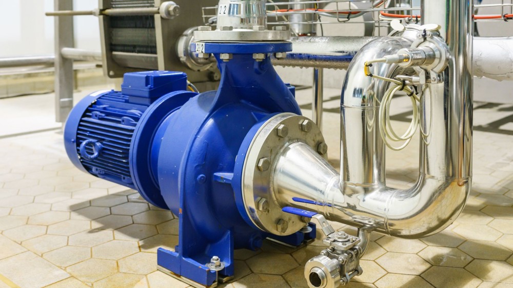
Centrifugal pumps move fluids by increasing pressure, and selecting the right pump depends heavily on understanding its performance curve—a graphical representation of how a pump behaves across different flow rates. Despite their importance, pump curves are often underutilized, especially by mechanics and operators who could benefit most from them. This disconnect is often due to limited access and a lack of understanding of the curve’s components.
What Is a Pump Curve?
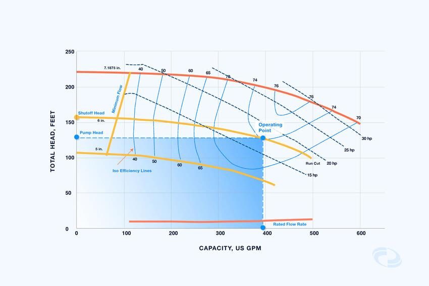
A pump curve illustrates the relationship between flow rate, head (pressure), efficiency, and power consumption. It helps identify the most efficient operating point and ensures the pump meets system requirements safely and effectively.
Key Components of a Pump Curve
- Flow Rate: Measured in gallons per minute (gpm) or cubic meters per hour (m³/h), it defines how much fluid moves through the system. Rated flow often includes a margin for uncertainties or future expansion.
- Head: The energy required to move fluid, measured in meters or feet. It remains constant regardless of fluid density.
- Brake Horsepower (BHp): The power needed to drive the pump, increasing with flow rate. Some pumps may show constant or decreasing BHp at high flows.
- Shut-Off Head: The pressure when flow is zero, determined by blocking the pump outlet.
- Minimum Flow: The lowest safe operating flow, defined by thermal, mechanical, and hydraulic limits.
- Run Out: The maximum flow rate the pump can handle, marking the end of the curve.
- Efficiency: The ratio of water horsepower to input power. Efficiency varies with flow and impeller design.
- Best Efficiency Point (BEP): The flow rate and head where the pump operates most efficiently, minimizing wear and energy use.
- Net Positive Suction Head Required (NPSHR): The minimum suction head needed to prevent cavitation, increasing sharply beyond the BEP.
How Pump Curves Are Created
Pump curves are developed through empirical testing under standard conditions. Manufacturers provide curves for specific impeller sizes and speeds, or multiple curves for various configurations. Typically, as flow increases, head decreases due to frictional losses in the system.
Factors Affecting Pump Curve Selection
Choosing the right pump involves evaluating:
- Shut-Off Head and pressure
- Head rise to shut-off (curve slope)
- BEP location
- Margin between available (NPSHA) and required (NPSHR) suction head
These factors ensure the pump fits the system’s hydraulic profile and operates reliably.
Why Pump Curves Matter
Understanding pump curves improves system safety, efficiency, and reliability. It helps avoid underperformance, excessive energy use, and mechanical failures. Operators and engineers who can interpret these curves are better equipped to select, maintain, and troubleshoot pumps effectively.
Final Thoughts
Learning to read and apply pump curves is essential for optimal pump selection and operation. By understanding flow, head, power, and efficiency relationships, and considering system-specific factors, you can ensure your pump meets performance expectations and supports long-term operational success.