Piping Systems FluidFlow3 - Heat Transfer

Heat transfer capabilities are included as standard within FluidFlow3. At each network element you can select from any of 3 heat transfer options (pipes have 5 options):
- Ignore Heat Loss/Gain
- Fixed Temperature Change
- Fixed Transfer Rate
- Do Heat Transfer Calculation
- Buried Pipe Calculation
For pipes, the software can also calculate heat loss/gain from the pipe. Pipes can be insulated with different types of materials using any thickness. Convection, conduction and radiation losses are calculated. This means you can use FluidFlow3 to optimize energy use by selecting the economic insulation thickness.
FluidFlow3 can model shell and tube exchangers, plate exchangers, coils and autoclaves.
100km Buried Seabed Pipe Heat Transfer Calculation

|
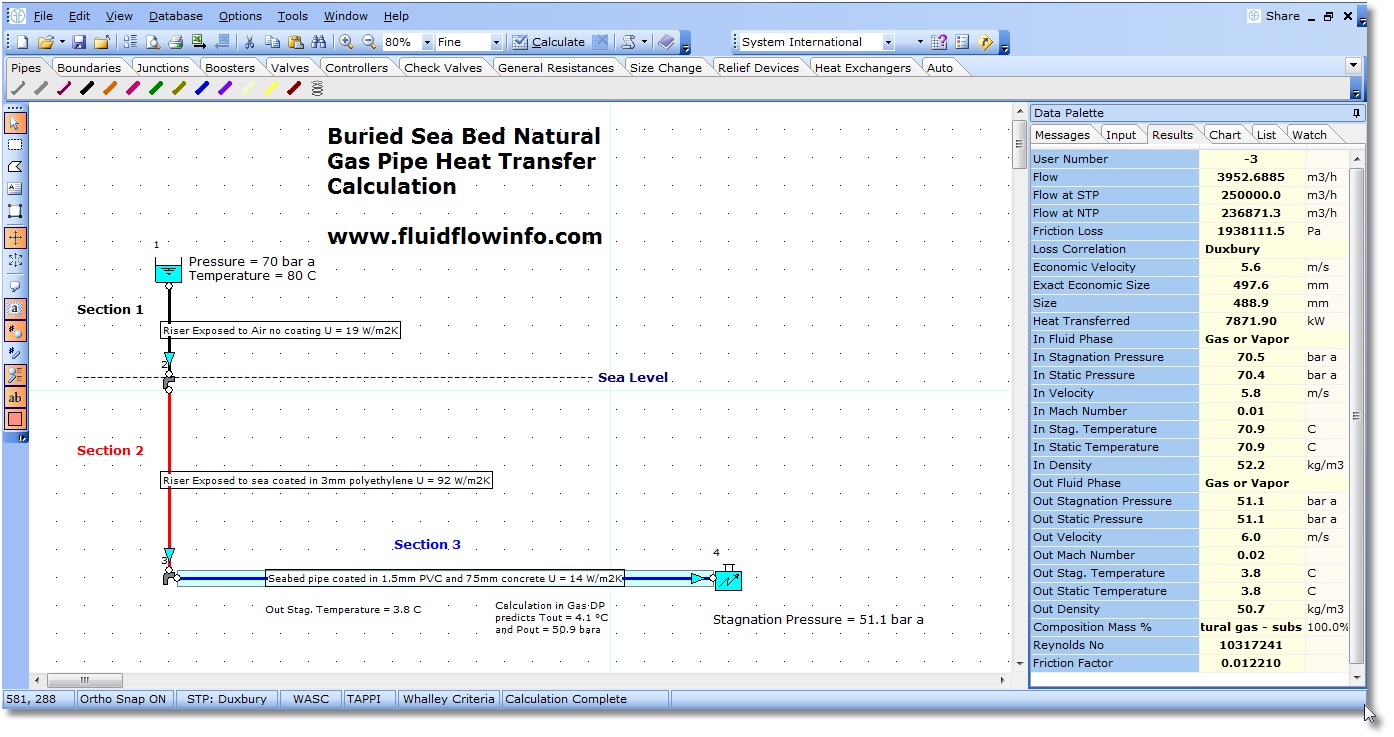
In this example system, we have an offshore natural gas production platform exporting gas at 80°C via a 100km, 20" buried sea-bed pipeline. The pipeline is modelled in three sections as follows:
- Pipe segment exposed to air (no coating).
- Pipe segment exposed to sea coated in 3mm polyethylene.
- Pipe segment running along the sea bed coated with 1.5mm PVC and 75mm concrete.
The overall heat transfer coefficients for each pipe segment have been established from the table of typical values. The air and sea temperatures used in the example are 10°C and 5°C degrees respectively.
This heat transfer example is one of many FluidFlow3 verification examples and the calculated results have been compared to
those available from the software package known as "Gas/dp" which is discontinued. Note, the results produced by the "Gas/dp"
program were in the past widely accepted as having a relatively high degree of accuracy.
|
Pipe heat loss calculation

|
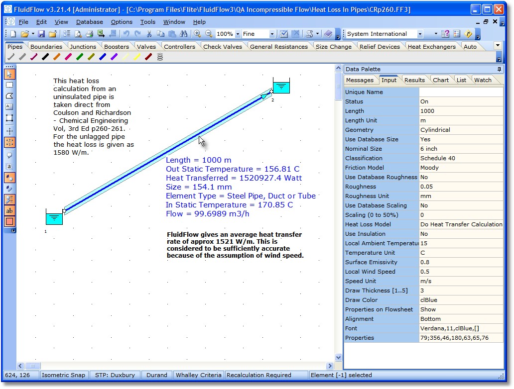
The example opposite shows the heat loss from a 1 kilometer length of uninsulated pipe.
There are over 300 QA example calculations made before each release of FluidFlow3. This is one of the verification heat transfer calculation examples.
A loss of 1520 kW over the pipe length represents energy wastage of over 1 million dollars per year.
|
Heat Exchanger Modelling

|
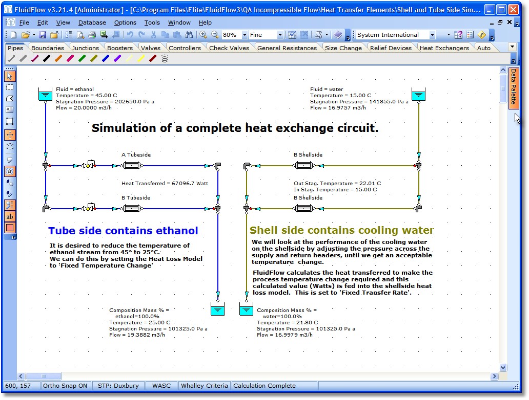
An example circuit showing 2 heat exchangers with full modelling of both the shell and tubeside. Usually modelling of one side is sufficient.
Several Pressure Loss correlations can be used including: Deleware method, using manufacturers loss data, or using a fixed pressure loss.
With the 2-phase module you can also consider condensors and evaporators.
|
Larger network showing the design of a computer data centre

|
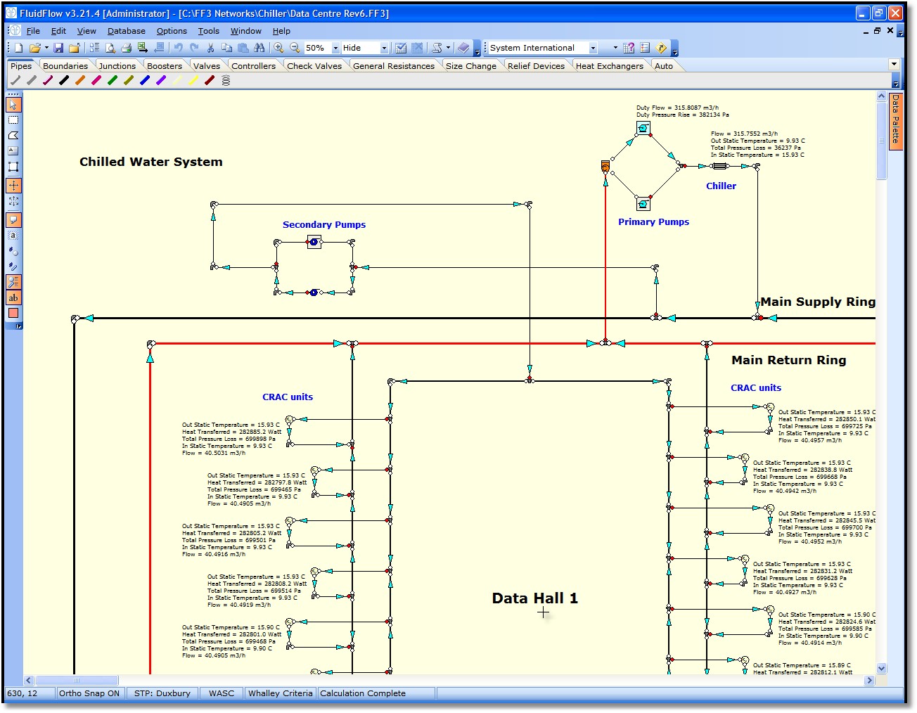
This network, shows how FluidFlow3 is used by a customer to model a chilled water cooling system in a Data Centre. Modelling of what happens due to pump failures is also considered in this model.
We have many other customers who model chiller circuits and/or district heating circuits using FluidFlow3.
One customer has sucessfully modelled the chiller system for Heathrow Airport and another the storage tank heating system at Europoort. Both networks contain over 5000 pipes and node and solve in a few minutes.
|
| 


